Living on the Edge
Happy New Year! Er, it’s a bit late for that, but considering my last update here was over four months ago… I suppose another couple weeks doesn’t hurt. If you read my previous post, you’ll know that I started an internship, and that’s what I’ve been doing for these past months. It’s certainly been keeping me busy, but when the holidays came around I finally found time to tackle one of the bigger things on my NooDS to-do list: 3D accuracy. I made a lot of progress and discovered some interesting things; it’s been a while, but let’s jump in!
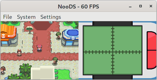
My quest for 3D accuracy began with this. If you’ve been around DS emulation for a while, you may be familiar with these black lines in the fourth generation Pokémon games that plague inaccurate 3D renderers. A post on the melonDS blog sheds some light on the issue; to summarize the relevant bits, the DS precalculates polygon edges and applies special rules to these pixels. Certain edges are skipped during rendering if the pixels are opaque, but only if edge effects are disabled; if edge marking or anti-aliasing are enabled, edges are always rendered so the effects can properly be applied. In the case of Pokémon, both edge marking and anti-aliasing are enabled, so it should be drawing polygons in all their edged glory. Unfortunately, when I first designed my renderer, I didn’t have edge effects in mind. By not properly calculating edge pixels, not only were these effects off the table, but edges weren’t included in the polygon fill either! This resulted in polygons always being drawn at roughly the size of hidden-edge polygons on hardware, which, as you can guess, was leaving gaps in Pokémon’s geometry.
Because I wanted to do things right, I first needed to better understand how edges are calculated on hardware. I wrote a simple homebrew program that would allow me to freely manipulate the vertices of a quad, as well as toggle the various attributes that affected edges; I’ll link it here in case it’s of use to anyone else. The first step of edge calculation is vertex traversal; looking at the melonDS article again, we can see that when rendering a polygon, the DS starts at the topmost vertex and follows the edges on both sides until it finds the ones that intersect with the current scanline. Looking into it further on my own, I found that the hardware only considers an edge to be intersecting if one of its Y values is greater, but not equal to the current scanline. This raises a problem for perfectly horizontal edges; they’re never considered to intersect! Only being designed to render convex polygons, the DS gets around this by assuming that horizontal edges can only ever be at the very top or very bottom of a polygon. If the current scanline is at either of these positions, the entire span between the two intersecting edges is considered an edge as well. However, if you try to draw a concave polygon with a horizontal edge in the middle of its Y-span, that edge will be missing!
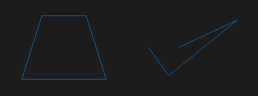
Now that I had vertex traversal down, it was time to nail the edges themselves. For a scanline-based renderer, edge calculation is a simple linear interpolation between the X coordinates of an edge’s vertices, using its Y coordinates and the current scanline. For Y-major edges (where the Y-span is greater than the X-span), it ends there, but for X-major edges, it’s possible for the edge to span multiple pixels on the same scanline. For this, a second interpolation is required to find where that pixel span ends; at least, that’s how I ended up doing it. With this I was able to draw wireframe polygons, but the edges weren’t quite right when compared to hardware. I spent a fair amount of time studying the edges and adjusting my renderer until it was mostly accurate, but there are still some minor imperfections with X-major edges so I won’t go into the details here. Instead of driving myself insane by staring at pixelated edges for the rest of my life, I decided that what I had was good enough for now and went on to investigate the curious phenomenon of edges becoming “dotted” when crossed.
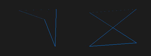
To understand the dotted edges, we first need to look at how the DS determines polygon orientation. Vertices are normally stored in counter-clockwise order; a polygon is considered front-facing if its vertices are counter-clockwise after being projected, and back-facing otherwise. This winding order of vertices is calculated before clipping by taking the 3D cross product of the second and third vertices (using the first vertex as a base), and then “projecting” that by taking the dot product of it and the first vertex. This works great for triangles, but quads have a fourth vertex that can complicate things. If the vertices used in the calculation form concave edges, the resulting orientation will be the opposite of what it should be. It gets even weirder when a quad has crossed edges; since orientation is calculated per-polygon, one part of the quad will always wind the wrong way. During vertex traversal, the DS uses a polygon’s orientation to decide which direction from the starting vertex is left, and which is right. If these directions are swapped, edge calculation malfunctions and the span across X-major edges is reduced to only one pixel. After replicating this behaviour, I was pretty satisfied with the accuracy of my edges.
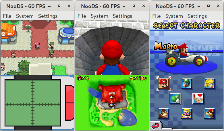
Finally, it was time to fill the polygons again. I was able to adapt my old fill code to the new edges without much trouble, and even implemented the special edge-hiding rules fairly easily. The renderer was back to a usable state, and the black lines in Pokémon were gone! I wasn’t satisfied yet, though; now that I had proper edge calculation, I could implement actual edge effects as well. I started with edge marking, which required reworking multi-threaded rendering to support a final pass that’s performed only once neighbouring scanlines are fully rendered; this was needed so that adjacent pixels can be checked when determining if a given edge pixel should be marked. I managed to come up with a solution that introduces minimal wait time, and it was pretty straightforward after that. Anti-aliasing was a bit more complicated; I’ll once again refer to a melonDS article for some explanation. In short, the DS keeps track of the pixels underneath edge pixels on a separate layer, and then blends these pixels together during the final pass using an alpha value based on the edge’s slope. It’s also worth noting that edge-marked pixels are special cases that always take on an alpha of 50%. Unlike with the edges, I didn’t spend much time perfecting the alpha calculations; I was mainly concerned with getting something that works, and I was happy with that for now. But I quickly noticed something that put a damper on my happiness; the black lines that I thought I had finally defeated had come back.
I knew my anti-aliasing wasn’t perfect, but surely it wasn’t that imperfect. I was stumped for a while, until something suddenly occurred to me. I did a quick hardware test and confirmed my suspicion; anti-aliasing doesn’t blend when the back pixel has an alpha value of 0 (put simply, the pixel doesn’t exist)! I knew there was more to it, though; Mario Kart DS has anti-aliasing on its character select screen even when there are no 3D pixels behind the characters. Further testing showed that when anti-aliasing has no back pixel to blend with, it instead simply sets the alpha value of the front pixel, preserving the effect by allowing it to be blended by the 2D engine. But if that’s the case, what prevents the black lines from showing up in Pokémon? The answer is simple; the game doesn’t have 2D blending enabled! While figuring this out, I also got a little sidetracked and worked out another somewhat interesting detail. When 3D blending is disabled, transparent polygons have their edges hidden as if they’re opaque; however, the alpha values are preserved, so if there’s nothing below them, you can still blend using the 2D engine and draw transparent hidden-edge polygons! In practice there isn’t much use for this, but it’s still a quirk of the renderer and there’s no harm in getting it right.
Aside from the edge work, there have of course been various other improvements from last time such as bug fixes, optimizations, and UI additions. One of the more notable changes was the implementation of sound capture; this allows copying output from the audio mixers into memory, similar to what display capture does for graphics. Since the DS sound hardware is fairly limited when it comes to effects, this allows for any number of effects to be applied via software by manipulating the captured audio data and then playing it back. Games like Super Mario 64 DS and Mario Kart DS use this to create a “surround sound” effect, although the latter seems to suffer from minor crackles with my current implementation so I still need to look into that. It’s also probably worth mentioning that I finally added an icon! It’s just something I whipped up in a couple hours, so it’s nothing mind-blowing, but it works well enough.

To avoid making this drag on for any longer than it already has, I’ll wrap it up here. The edge work turned out to be more of an adventure than I expected, but it was something that I’ve wanted to take care of for a while, and I’m glad I finally did it. I think NooDS is finally at a point where I could genuinely recommend it as a way to play DS games on other platforms, and that’s pretty cool. I still enjoy working on it, even if I’ve been finding less time to do so lately, and I still have so many things I’d like to do! Now that this is done, the next big thing I’d like to tackle is finally getting some sort of timing system going. NooDS is probably the first emulator to come this far while still considering everything to only take one cycle! Well, that’s it for the great comeback post; see you next time, whenever that may be.